PROJECTS


PDF Low-Cost Audio Micro Ohm Meter
System Overview
 published with permission
The Audio Micro Ohm Meter uses synchronous detection to measure low value resistances. The circuit provides a variable frequency audio tone to indicate the resistance under test. Such a tone is invaluable when troubleshooting shorted tracks on multi-layer circuit boards.
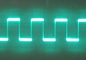
Timer U4 generates a 9V 1KHz square wave carrier signal that is injected into Rtest at J1. AC amplifier U2A amplifies the signal. The sensitivity of the circuit may be adjusted by potentiometer R16, which changes the AC amplifier gain over a three to one range. The amplitude of the 1KHz waveform at the output of U2A is proportional to the resistance of the resistance under test, Rtest.
A synchronous detector formed by U1A, U1B, and U2C demodulates the carrier signal. U1A and U1B are driven by out-of-phase signals PHI and –PHI. Signals that are at the same frequency as the PHI and –PHI drive signals are integrated, and others (such as 50Hz or 60Hz) are rejected.
Timer U3 functions as a voltage-controlled oscillator that converts the demodulated signal into a variable tone output. U2B turns off the tone when the resistance exceeds several ohms to conserve power.
A voltage output proportional to Rtest may be taken from the output of U2C. Note that any track resistance between the Rtest GND node and the U1 GND node will be included as part of the measurement. If a calibrated output is desired, U2C may be replaced by an instrumentation amplifier to eliminate this common-mode resistance error and +V to U4 should be regulated to make the carrier signal a constant amplitude independent of power supply variations.
The circuit runs off of a single 9V battery and draws about 4mA when the tone is OFF and 10 to 20mA when the tone is ON, depending on the type of speaker used.
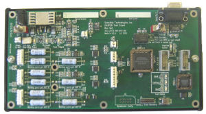
Bolton Engineering, Inc. was contracted by a local instrumentation company to construct a low-cost Audio MicroOhm Meter to be used in detecting circuit board short-circuits. Based completely on inexpensive low-power “jelly bean” CMOS ICs, this design ran for days and days off of a single 9V battery. The total material cost was well under $5.